When Ted Hart published his design for a flat 2m EH antenna, many letters began to come in from many radio amateurs able to reproduce it for themselves with good results. The 2m flat EH antenna is an ideal antenna in which to examine some of the concepts and properties behind EH antennas. However, not all of radio amateurs use nor have equipment and simple test gear for 2 metres. I decided to investigate the properties of the EH antennas further by firstly, scaling the antenna for 14 MHz and secondly, building two SIZE- IDENTICAL flat antennas, but tune one as an EH antenna, and the other as a short flat dipole? I thought this was an interesting idea because in one sense, I wanted to produce a short flat dipole based on the design parameters of an EH antenna as much as possible. Theoretically and practically it is impossible due to the inherently different antenna geometries /feed arrangements etc. of an EH versus a dipole design. But I thought it an interesting concept to try and did it anyway.
I reproduce all of the calculations of antenna design to ensure that you are clear in how I calculated the various antenna parameters. First, I calculated parameters for the flat EH antenna using the programme from VK4ANW. The actual design parameters for the EH antenna are shown below in Pic. 1. These data were published on my website (Russian language) two years back and flat EH antennas based on these parameters have been reproduced by many radio amateurs, with good results. For example, on my 14 MHz flat EH antenna I made over 4000 QSOs with all continents using a transmitter power of just 40 watts.

Pic. 1 Calculation of flat EH antenna for 14 Mhz.
The flat EH antenna was constructed and tuned and its operating characteristics were determined using miniVNA software (see of Pic. 2). The passband of the EH antenna turned out to be 910 KHz (at a level of plus/minus3db), and 1,1 MHz (on the level of SWR=1:2) which is even better than predicted.

Pic. 2 Passband characteristics of the 14 MHz flat EH antenna.
Thus, one antenna is built, tuned and its operating parameters characterised. It was now time to make the second antenna, identical in size to the EH antenna but adjusted as an ordinary very short dipole.
Previous visitors to my website will remember such experiments on very short antennas (equal in size to EH antennas) were made in the field, and compared to EH antennas. That was 2.5 years back and a great deal has changed since, but, nevertheless, it is necessary to go back to past events. "Reiteration - a mother of studies" is a very popular Russian saying. We will study further, it is never too late. Getting back to the short flat dipole, I used the program MMANA and input size parameters identical to the flat EH antenna. A file of the program MMANA is here. When assessing results from MMANA it is necessary to take into account some features of this program, namely, that calculations of resistance and (reactive) parameters at the nearfield do not account for ground losses. Losses in ground are taken into account only at the calculation of antenna orientation. It is also worth pointing out that it is not possible to model EH antennas in MMANA because the program does not take into account those physical features on which EH antennas work i.e. bias current of displacement (it is not needed for classic dipole design). I show a screenshot of the calculations from MMANA for those who use this program.

Pic.3 Information entered into the program MMANA for a dipole.
Pic.4 Results of calculations of very short dipole for 14 Mhz in the program MMANA.
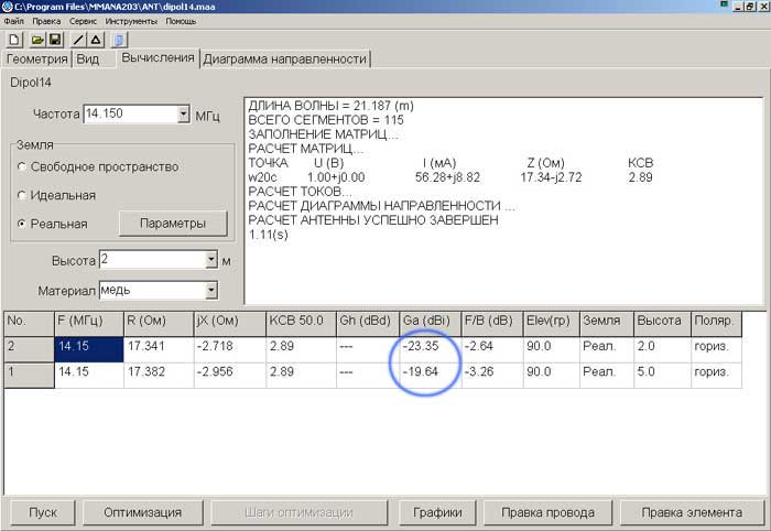
Pic. 4 Results of calculations of very short dipole for 14 Mhz in the program MMANA..
Clearly, that for the concordance of such a dipole (with resistance of transmitter using a cable), it is necessary to use a chart of concordance. We can take advantage of a feature in MMANA and determine L-C is in-use concordance on the following chart:

Pic. 5 Chart of concordance and calculation information for Dipol on 14 Mhz in the program MMANA.
What now remains is to do a chart of concordance and tune the antenna. Now we can begin this work. Tuning the chart of concordance (for this purpose certainly it is very desirable to have some form of antenna analyzer i.e. VNA, MFJ-259, A-330, "miniVNA" etc., it is necessary to remember that tuning is critical. For those who have tuned a short dipole will know using concordance charts that this process is not quick. Finally, the short flat dipole was constructed and tuned. Its characterisation is shown in Pic. 6

Pic.6 Characteristics of a very short flat dipole.
If we will compare this picture to the picture of Pic. 2, will see that passband at flat EH antenna and shortened Dipol, has a difference in 7 of one times! That antenna identical sizes and spool winded an identical wire (mechanical information of aerials and spools is resulted below).
It is the first moment which must compel to think and weigh all of difference between Dipol and EH, and such moments yet it will be very much, but about them farther.
If we compare Pic. 6 to the picture of Pic. 2, we can see that the passband for the flat EH antenna versus the shortened dipole has a difference in ratio of 7 to 1! Bear in mind that the antennas are identical in size, including amount of spool winded and identical wire dimensions (mechanical information of aerials and spools is resulted below). It is clearly a moment which must compels you to think and weigh up all of the difference between a dipole and EH. I will come back to these points shortly.
Both antennas look very simply – ALMOST IDENTICAL! see of Pic. 7. Although they appear identical, there are huge differences in the passband of the EH versus the short flat dipole!! It is a cause for much reflection.

Pic.7 Original appearance of shortened Dipol and EH antenna
(on a photo Dipol yet without the chart of concordance)
Clearly, the EH antenna (on the right) has one spool based on the "Star" design. It is also possible to do similar comparisons using two spools evidenced using the L+L or L+T, designs. The inductance of the “Star” design flat EH is equal (see Pic.1), to 14,2 microHenry and tuning made possible by a tap on the second turn of the tuning coil. Two extending spools are evidenced for the shortened dipole, (see Pic.3), at 14 microHenry, and yet, the chart of concordance (not shown in article) with parameters, (see Pic.5), i.e. the spool has 0,3 microHenry and condenser at 300 Pf (tuning is possible).
The sizes of antennas are presented in Pic.8. I repeat, that both antennas have identical sizes.
Pic.8 Size of "dipole" and EH antenna..
Now for some construction details: The EH antenna has a spool of wire wound on a polypropylene white pipe framework of 32 mm diameter. The tuning coil has 20 turns of wire with diameter 0,69 mm, and a ‘tap’ is taken for tuning on the second turn of the tuning coil. The dipole has two extending spools, wound on a grey polypropylene framework also 32 mm in diameter. It has 16 turns of wire with diameter 0,69 mm.. In addition, the chart of concordance is used on L-C (Pic.5) in an order to co-ordinate entrance resistance of the shortened dipole, with a value of about 17 Ohm (see calculations in MMANA. Entrance resistance depends on good quality calculations of earth. With a cable of 50 ohms a spool is wound on a polyethylene former (with diameter about 10 mm) and 5 coils of that wire by a diameter 0,69 mm. A condenser with a capacity 270 Pf (the selection of capacity and inductance is possible at tuning, on a minimum of SWR), on tension 500 volt.
Tuning, background to tuning EH antennas can be found in other pages of my website. Similarly, summaries of tuning short dipoles can be found in the literature. Once again it is best to repeat that the EXTENDING spools are used in shortened dipoles, in order to ensure that its electric length is resonant at its chosen frequency which is very different to the EH concept of antennas. In EH antennas, a tuning coil is used to achieve resonance of LC which results from the capacity between the plates and this additional spool (the reactance of spool is compensated by a reactance and capacity between the elements of EH antenna).:
EH antenna:
- Central of frequency - 14,100 MHz
- SWR - 1:1,02
- passband - 1100 KHz (on SWR=1:2)
- Efficiency 99% (calculation)
Shot Dipol:
- Central of frequency - 14,140 MHz
- SWR - 1:1,08
- passband - 156 KHz (on SWR=1:2)
- Efficiency 5% (approximately)
We can now go onto comparison of these antennas. The EH antenna and very short dipole were connected to a transceiver and characteristics of their respective field profiles measured. What will we see? see of Pic.9.) Moreover, two short videofiles were taken which clear show differences in the fields from flat EH and very shot Dipol. Videofiles are here: Very shot Dipol (3,4 Mb - mpg) Flat EH antenna (2,2 Mb - mpg).
As the saying goes, all is visible to the unarmed look.

Pic.9 Fields from very shot Dipol and EH antenna.
Differences between the antennas are significant as we also saw with differences in passband curves.
Interestingly, if we turn the antennas in a horizontal plane we can measure their nearfield profiles? (see following Pic.10)
Pic.10 Signal profile about 5 meters distance from antennas.
Diagrams of very shot Dipol and flat EH antenna, presented on the pictures of Pic.9 and FPic.10, different and far, although antennas are identical in a due form and geometries.
Unfortunately, the diagram of antennas orientated (as above) for the distant field have not been profiled but signal levels at a distance of 20 wavelengths (approximately 400 meters) were measured. I thought it interesting to include at this stage the signal profile from a full size wire dipole cut for this band. of this band. The ICOM-718 was used in these tests with an output power of 10 watts using CW. For receiving signals I used an Yaesu FT-817, (with AGC off) with a 50 cm wire for an antenna. Data from these tests were transferred to a notebook that ran a programme called "Spectran". Data were saved in a file to enable detailed analysis. I combined signal strength data for all three antennas (see Pic.11).
Pic.11 Combined screenshot levels of signal from full size dipol, flat EH and short flat dipole.
The screenshot of plotted RF signals show large differences between antennas of approximately 5-6 dB. Although a distance of 20 waveslengths is not particularly far, it gives you a good idea of how each antenna fares relative to each other. Please note that the Yaesu FT-817 is not a "measurings receiver" and signal strengths must be viewed purely relative to each other. . It is also interesting to look at the background signal generated for each antenna with a difference of approximately 3 – 3.5 dB between the full size dipole and EH antenna.
From this stage it is also instructive to see how these various antennas perform in a real-world amateur environment. Mounted on a roof at a height of 8 meters above ground, either a flat EH, classical EH cylinder or a very short dipole were put through their paces. (see Pic.12 below).

Pic.12 Flat EH (or very shot dipole) and standard cylinder EH on the roof.
Firstly, I asked for on-air comments from other amateurs as I changed between antennas. I used my ICOM-718 for these tests, (80 watts on SSB and CW, and 40 watts on PSK-31 and RTTY). My first contact was with RZ1ZZ although propagation at this time was not favourable. When changing from the EH to the very short dipole I was asked whether or not I had turned my power amplifier off!! Overall, differences between the EH and the short flat dipole were approximately 3-4 S point in favour of the EH. I will continue work using CW and PSK-31 modes at a later date. A fews ten of QSO was conducted with RA1, RA4, RA9, DL, OK, PA, etc. More precise estimates of received signal strengths can be pbtained using PSK-31, because most programs give information on signal strength plus a correlation between signal/noise. I then connected the antennas to my Yaesu FT-817 (with an output power of 5 watts) in order to work in QRP mode. As an experienced CW telegrapher I preferred this mode of communication over PSK31 and differences in transmitted signal strength were once again in the region of 3 – 4 dB points in favour of the EH relative to the short flat dipole.
| S-meter |
Level of signal dB |
Level of signal, microVolts |
| 9+40 |
-33 |
5000 |
| 9+30 |
-43 |
1600 |
| 9+20 |
-53 |
500 |
| 9+10 |
-63 |
160 |
| 9 |
-73 |
50 |
| 8 |
-79 |
25 |
| 7 |
-85 |
12,5 |
| 6 |
-91 |
6,3 |
| 5 |
-97 |
3,1 |
| 4 |
-103 |
1,6 |
| 3 |
-109 |
0,8 |
| 2 |
-115 |
0,4 |
| 1 |
-121 |
0,2 |
Tab. 1
I now return to Pic.4. In the column called "Ga" it is possible to see the calculation value of the short flat dipole and compare it to the real difference in signals, of approximately 3-4 points. It is interesting to note that the calculated and on-air signal strengths (see Table 1) coincide fully. But another very important conclusion is in relation to gain relative to an isotropic antenna. The flat EH antenna has a gain higher than a theoretical isotropic radiator and is 2 db less relative to a standard full size dipole. Thus once again these short tests confirm that EH antennas (as small as they are) have similar performance to that of a full size dipole. It was also interesting to note that the cylinder type EH and the flat type EH perform as well as each other in real-world situations.