This document describes a 2 meter antenna the reader may build and test to validate the
performance, and to learn more about the EH Antenna. To make life really simple, a flat
antenna was chosen. Tests in an anechoic chamber indicate that it has close to the same
performance characteristics as a round antenna. A round one this size would have a
diameter of 3/8 inch. I chose that size to make it easier to build than a smaller one and it
has more bandwidth, so it will be less critical.
On the last page I have included the calculations for the antenna. The only difference is
that the diameter should be multiplied by . to give the width (effective circumference)
for the flat antenna. It will work if the copper is glued to a piece of paper, but it is
preferable if you glue the copper to a piece of clear plastic. For the test antenna I used a
plastic ruler. Run the feed line out to the side of the antenna and down to the radio. This
is illustrated in the photograph below. For testing tape the ruler to the radio
I suggest that the tuning coil and the twisted pair feed line be made of #24 or smaller
enamel covered wire because that is readily available at Radio Shack, or at a local motor
rewind shop. Tap the tuning coil at about 1 turn from the cold end. Spread the wires as
needed for tuning and matching.
The twisted pair is simply a pair of wires twisted together. The amount of twist is not
critical, but I use about 3 complete turns per inch because that is easy when using an
electric drill. To prevent distortion of the radiation pattern be sure to use an ohm meter to
validate that the ground end of the tuning coil is the same as the ground on the radio.
The test results from the example antenna are documented in the attached analysis. I hope
you will install the antenna on your handheld radio and compare the communication
range against the standard antenna. Please share the results of your experiment on the
forum.
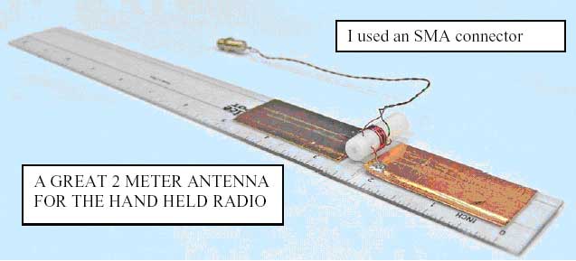
Pic. 1 Flat EH antenna 145 Mhz.
As a general comment, tuning and matching the antenna takes only a few minutes if you
have the proper test equipment, i.e., a network analyzer. If you only have a field strength
meter it takes longer to change frequency on the radio to verify the frequency of
maximum radiation and to adjust the tap for best match.
FOLLOWING IS A DESIGN PROGRAM FOR AN EH ANTENNA
SPECIFY THE PARAMETERS IN THE BLUE CELLS
| Frequency |
146 |
MHz |
flat 30 мм |
| Cylinder Diameter |
9,5 |
millimeters |
. |
| L/D ratio |
6 |
. |
. |
| Total Length |
124 |
millimeters |
. |
| Total Length |
12,4 |
centimeters |
. |
| Capacity |
2 |
pFd |
LINE A |
| Inductance needed |
0,6 |
uHy |
. |
| Coil Capacity |
0,86 |
pFd |
. |
| Total Capacity |
2,9 |
pFd |
. |
| Modified Inductance |
0,4 |
UHy |
. |
| Reactance |
545,1 |
Ohms |
. |
| Coil Diameter |
9,5 |
millimeters |
. |
| Wire Spacing |
0,35 |
millimeters |
#28 wire |
| # Turns |
6,5 |
Turns |
. |
| Coil Length |
2,5 |
millimeters |
. |
| Wire Length |
18,3 |
centimeters |
. |
USE THE ABOVE TO BUILD AND RESONATE THE ANTENNA AND TO MATCH IT
TO 50 OHMS. INSERT THE MEASURED BANDWIDTH AFTER MATCHING.
| Measued +/- 3 dB BW |
19400 |
KHz |
| Measued 2:1 VSWR BW |
6000 |
KHz |
| Radiation Resistance |
72,4 |
Ohms |
| Antenna Q |
7,5 |
. |
CALCULATE ANTENNA EFICIENCY |
| Assume coil Q |
200 |
. |
| RF Resistance in coil |
2,7 |
Ohms |
| Antenna Efficiency |
96,4 |
% |
| Antenna Efficiency |
-0,16 |
dB |
ANTENNA POWER PARAMETERS |
| Transmitter Power |
5 |
watts |
| Transmission Line Z |
50 |
Ohms |
| Transmission Line voltage |
15,8 |
Volts RMS |
| Transmission Line Current |
0,3 |
Amps RMS |
| Current between Cilinders |
0,3 |
Amps RMS |
| Voltage between Cylinders |
143,2 |
Volts RMS |
| Voltage between Cylinders |
401,0 |
Volts P-P |
CONSTRUCTING AND TUNING THE FLAT 2m EH ANTENNA
May/2007
Vlad Kononov (UA1ACO)
UA1ACO (Vlad), built the 2m EH flat antenna and carried out further experiments. The antenna was made to specification as detailed in TedТs article (above). To test this antenna, I used a "Kenwood TH-F6A" with output power up to 50 milliwatts (using an internal attenuator -20 dB).
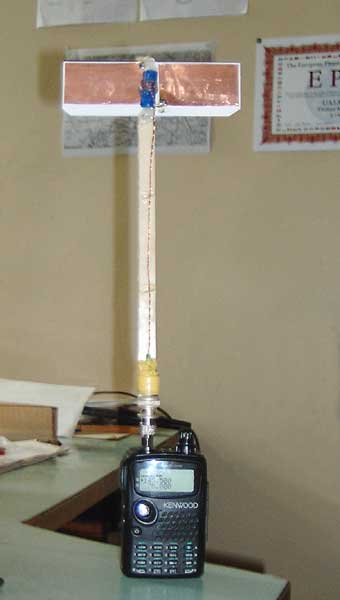

Pic. 2 Flat EH antenna 145 MHz built by UA1ACO.
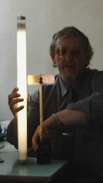
Pic. 3 A fluorescent lamp (20 watts) lights up brightly close to the EH antenna using an output power 5 watts from my Kenwood.
Two experiences.
First Experiment:
1. I installed the standard СrubberТ antenna on my Kenwood TH-F6A .
2. Two receiving stations approximately 1kilometre (about 0.7 mile) away were used to determine signal strengths. One of the receiving station S-meter was down at least -10 dB (stations were calibrated on HF generator).
3. The standard СrubberТ antenna on my Kenwood was replaced with the flat EH antenna.
4. Signal strengths at the receive station increased in gain by more than 10 dB.
Second Experiment:
1. The "Kenwood TH-F6A" was used as the transmit station. The receive station was a radio receiver with quartz stabilization. When the AGC was switched out, the dynamic range was at least 60 dB using an antenna with a length of 10 centimetres (4 inch). The receive signal generated by the radio receiver was then fed into a digital indicator (with an accuracy of 0.1 dB).
2. The distance between the transmit and receive stations was 8 wavelengths i.e. 16 metres or 17,5 yards.
3. A full-sized dipole was connected to the "Kenwood TH-F6A" and the signal received by the receiver was used to normalise subsequent signal strengths i.e. 0 dB.
4. Firstly, the standard СrubberТ antenna was connected to the "Kenwood TH-F6A" and the signal on the receiver (after normalisation) was -5 dB.
5 The standard rubber antenna was replaced by the flat 2m EH antenna with an increase in signal strength of +3 dB.
Experiments were also carried out to measure the E and H fields using sensors. The results of these experiments are presented below (see Fig.3).
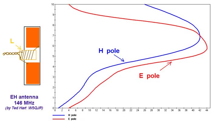
Pic. 4 Flat EH antenna 145 MHz E and H pole. I think, that all remembered graphs of the distribution E and H fields beside of Dipole? Really, there is something general?
Levels of the E and H fields from a flat EH antenna and full-size dipole in a near and distant area for the 145 MHz band.
Several years ago I was interested in measuring the E and H fields from EH antennas and compare them to the fields generated by a standard full-size dipole. I carried out a few such experiments with one small theoretical problem, the distances of the EH field measuring devices to the transmit antenna were small, no more than 2-5 wavelengths. Clearly, it is not possible to come to any firm conclusions based on near-field experiments and it would be much better to conduct some experiments at the far field, (there is little available information in the literature).
I then carried out a number of far field E and H field experiments at varying distances. The antennas used were a standard full-size dipole versus the flat EH antenna to assess both transmit and receive characteristics. Summarising a lot of data, it is possible to say that the full-size dipole and EH antenna appear to work in almost identical fashion i.e. signal/receive strengths were sometimes slightly higher, sometimes slightly lower, relative to each other. But this comparison was subjective, using my ears, or the dB output from a measuring spectrum device used for Psk31work. It was now time to carry out more meaningful, quantitative assessments of relative E and H fields from these completely different antennas.
I carried out an experiment to determine the relative strengths and characteristics of the E and H fields from a flat 2m EH antenna and a full-size dipole to a distance of 150 wavelengths for the 2m band. However, the measurements were conducted in a long alley along which stood metallic lighting lanterns at distances of approximately 20-25 meters from each other. Naturally, there will be some re-radiation from these СartifactsТ which may sharply distort resultant measurements. It is sufficient to say that such measurements do not convey the full picture of what is actually happening yet it can be seen that some general characteristics between the two antennas emerged.
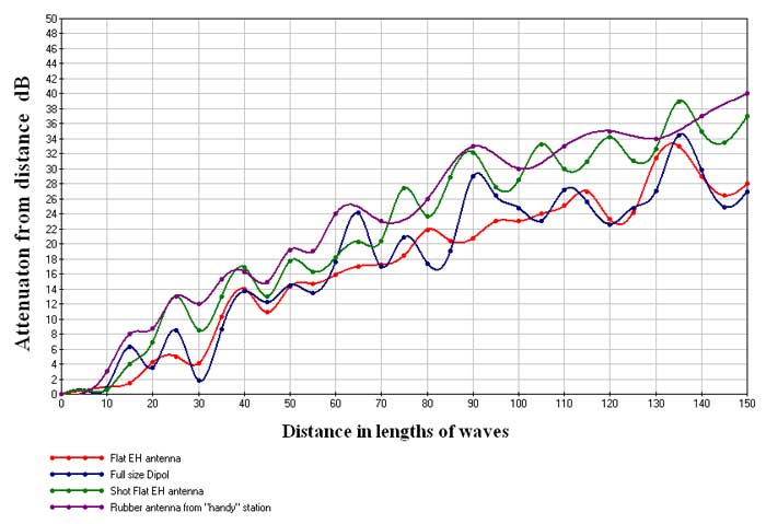
Pic.1 Measurements of the level of E and H fields along an alley with metallic lantern СartifactsТ.
Firstly, the above example shows, that in order to come to any meaningful conclusions on field strength attenuations with distance experiments, an awful lot of work is required. The above experiments need to be repeated in differing environments, (in terms of terrain, flat, urban etc.) in order to assess significant differences in performances between antennas and to draw firm conclusions. Some time passed after these initial experiments but I was unable to find the time to carry them out.Finally, July and the warm weather arrived and I found myself on an air field with a complete set of measuring devices and antennas, for the measurement of E and H fields and their comparative levels.
Materials:
- 2m transmitter using 145,5 MHz with an output power of 1 watt (feed from an accumulator, with a filter).
- Flat EH antenna; SWR = 1:1,23
- Flat EH antenna shortened; SWR = 1:1,22
- Full-size dipole cut for 145,5 Mhz; SWR = 1:1,03
- Rubber antenna from "handy" station 145 MHz; SWR = 1:1,38
- Receiver instrumentation on 145,5 Mhz with the quartz stabilizing and linear dynamic ranges of 60 db (without AGC), antenna vertical (15 cm.), feed from a separate accumulator.
- Measuring of output of receiver - digital 4 bit "M890G" (accuracy of counting to 0,1 db).
Antennas used in these experiments (see Pic. 2 below).
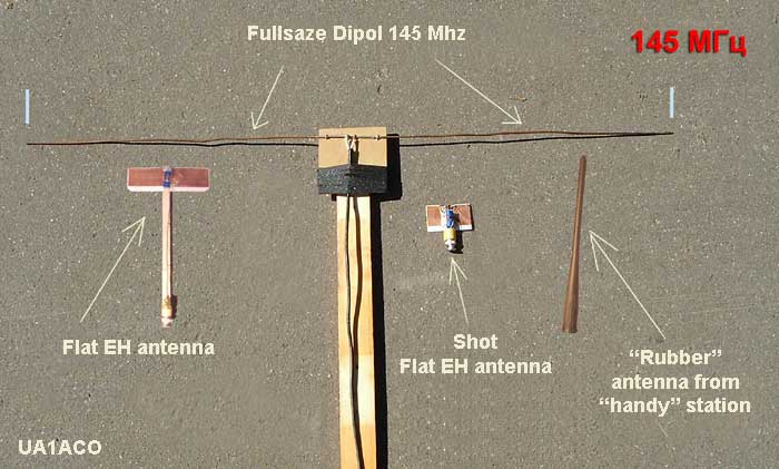
Pic.2. Experimental antennas showing their relative physical sizes.
The experiment itself was very simple: each antenna in turn was used to transmit signals which were picked up by a measuring device in the field i.e. a receiver. Signals were measured at intervals up to a distance of 230 wavelengths (~0.5 km). At each distance interval a horizontal dipole (oriented for MAXIMUM of radiation) was used to receive signals. Original appearance of receiver (set on a dielectric stick) and TX with an accumulator (in the right lower corner of picture) can be seen in Pic.3
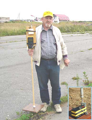
Pic.3 Original appearance of receiver on a stick and transmitter (in the right lower corner of photo).
Data on the E and H field levels from different antennas - Pic.4
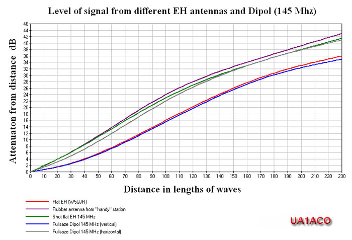
Pic.4 Change of the field level from different antennas, depending on distance.
1. The graph above shows that a stable "flow" of curves, begins at distances between 100-120 wavelengths. It is here that the Сdistant fieldТ begins, if it can be so named. It is also necessary to note that measurements were conducted with 8 different antennas only, yet the curve characteristics for all antennas are almost identical.
2. The graph clearly shows that the field levels from the full-size dipole and flat EH antenna coincide almost identically. This says a great deal about the geometrical or relative physical sizes of the full-size dipole and flat EH antennas and their respective performance in the field. These graphs confirm once again that in terms of efficiency, EH antennas are comparable with full-size dipoles and in some respects exceed the dipole in some antenna parameters. But if EH antennas were modelled in the program MMANA, we will get -20/-28dB. It is not confirmed practically (and a cable at antennas is not present, that about could radiate - aerials were set directly on a transmitter, and next to antennas nothing was, that something could re-radiations' in the naked field). The program MMANA bias current does not take into account, which principle of action of EH antennas (operating theory of EH) is based on, and models them as shortened "vertikaly" (classic dipole).
3. Now, if we remember an article on this site (see Russian EH site, sorry), in which the comparative tests of an EH antenna and handy "rubber" antenna are described using a hand portable station. Differences between the EH antenna and "rubber" antenna in those experiments was 6-10 dB. These values very nicely confirm that found in real field measurements conducted already once or twice, in different terms.
4. Even the little short flat (half size) EH antenna, worked better than the standard "rubber" antenna even though it is physically four times smaller! Yes, I am not yet able to properly tune EH antennas :) and as yet, do not fully understand how they work. When I do understand more of the theoretical concepts behind these antennas I will be able to formulate hypotheses to test and drive forward why the EH antennas perform in the way that they do, relative to a full-size dipole!!
73! Vlad UA1ACO