Much of the low band HF is full of clicks and other strange noises. I began to listen to 10 MHz and found lots of activity and interesting stuff to listen to. At that time I used a 42 metre long wire fed into an ICOM AT-180 tuner and my transceiver was an of ICOM-7000. Although I had not had many QSOs on this band I was intrigued and quickly decided to construct a quick and easy flat EH design, not the EH cylinder design. From the onset, construction took just 3-4 hours work. I found all the materials I needed from what was lying around in the shack. Following its construction I left it in the garden untuned due to work commitments.
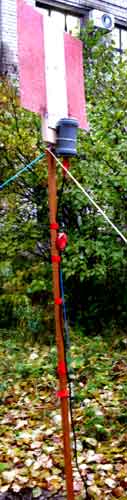
Original appearance of the prepared antenna on the photo of Pic.1
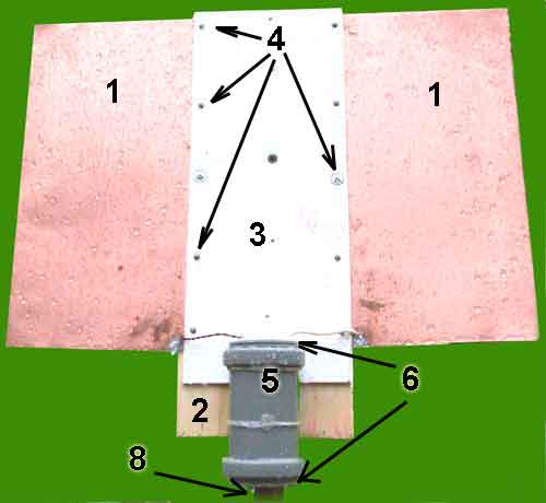
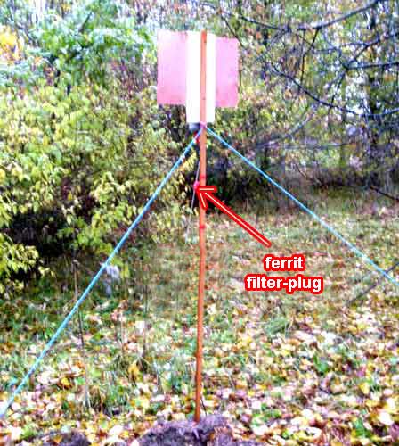
Pic. 1 Flat EH antenna on 10 MHz band.
Materials required for construction:
- Two sheets of copper measuring 180 x 315 mm, no less than 1 mm thick
- Wood board (it is possible to use aplastic, for example tekstolite) measuring 150х400 mm about 10 mm thick
and in about 10 mm thick.
- Bubble wrap plastic about 3-4 mm thick i.e. polypropylene, tekstolite, or similar, measuring 150х320 mm
- About 10 tapping screw (if possible M3 or M4)
- polipropilenovuy muff with a diameter of 50 mm - from the shop of the sanitary engineering company
- 2 of choke to this muff.
- Polypropylene pipe (grey or white) with a diameter 32 mm and 100 mm long
- Antenna connector, 1 SO-239 chasis mount
- Wire with a diameter of 0,85 mm i.e. #21 and 8m long
- Glue gun Ц (very important)
- Soldering iron
Draft of EH antenna, Pic. 2
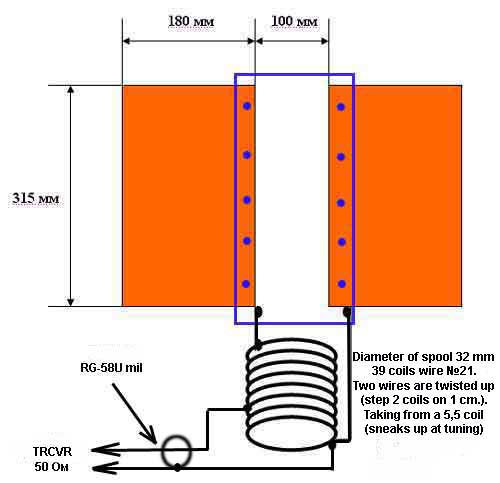
Pic.2 Draft over of EH antenna.
an inim color is rotin a board and screw
Each number on the picture corresponds to its number in the Materials List. Construction is relatively simple and does not require any special explanations. We scissor out on a metal two sheets of copper measuring 315х180 mm (plus or minus 5 mm Ц this is not too critical). Make a piece of board measuring 150х400 mm (dimensions not too critical). Then we prepare a piece of plastic measuring 150х320 mm..
We then begin assembling the basic elements of antenna: we put a board on a table and lay on its top, two sheets of copper. (see Pic. 2). The distance between the sides (315 mm) of copper foil is 100 mm. We then bind the copper foil to the board. We now place the plastic piece at its base and connect all of this open "sandwich" screw. The half of antenna for us is ready!
We now build the tuning coil. The tuning coil will sit inside its СmuffТ to protect it from the rain. Use whatever ingenuity you can to ensure a rain-tight protective box for the tuning coil.
The SO239 chasis mount connector sits at the base of a tube (see pic below) on how it looks like. Under one of the SO239 screws, solder a lug which will form the connector for the "cold" wire (bottom of the tuning coil wire) from the tuning coil. Tip: Ensure you have a good solid ground connection between the SO239 and base of the tuning coil here otherwise you may experience СunusualТ operation from your antenna in 3 Ц 6 months time. I prefer to solder the ground lug but the choice on how you do it is yours.
At the top of the muff, drill two holes (diameter 2-3 mm) for two wires which you solder at the base and bottom of the tuning coil respectively, (these wires can be seen from above muffs on the picture of Pic.1) Tip: After final construction and tune, please fill these holes with glue to ensure moisture does not get into the muff.
Now we can build the coil. We have one piece of polypropylene pipe 100 mm. by a diameter 32 mm. Firstly, we cut off two pieces of wire #21 (0,85 mm) 4 metres long for each wire. We twist up these two wires along its length (I used elektrodrel for these aims). The amount of twist per centimetre not important i.e. I use 2, 3 twist/centimeter. We then fasten the wires and leave an extra 100-150 mm (free end) wire at the end of the coil. You must ensure you drill a hole to fix the twisted pair of wires. We then wind 39 coils onto the former and fasten the second end, leaving an allowance of about 100-150 mm (see PIc. 2). Using these wire dimensions it should be possible to get the antenna at its initial resonance (and minimum of SWR) by moving apart or compression of the coil rather than cutting the length of these wires to achieve resonance. We solder wires from the coil to its connector. We fasten the tuning coil on its lower muff using a glue gun. Big tip: - the coil must be firmly glued to the lower tube enclosure! Original appearance of coil, sat and glued to its enclosure (see Pic.3 below)
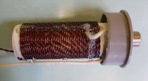
Pic. 3 Coil sat and glued on its enclosure.
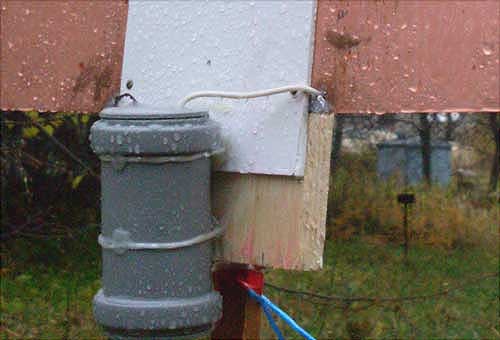
We then connect all the СexternalТ wiring to the tuning coil (see Pic. 4 below and Pic.1 and Pic.3). At this stage do not put the muff on the tuning coil. It is now time to carry out the tuning of the antenna by squeezing or moving apart the wires at the top of the coil (to alter resonance) or SWR (with concurrent maximum field strength) at the base o the coil. When tuning is achieved you should have an almost perfect VSWR of 1:1 at the resonant frequency of your choice with maximum field strength: all three must come together to achieve an efficient antenna. We then glue the wiring into position to ensure the tune stays where it is. What is left is to connect the "Cold" wire to one of the copper plates and please note that it is desirable to connect the wire to the edge of the copper plate i.e. no more than 4-5 mm, no more due to very large voltages). Please note an with reference to Pic 3, the wire to the copper plate must not touch the wire on the tuning coil and this is achieved by СspottingТ glue along the tuning coil to bed the Сcold; wire into position. After tuning the only thing left is to assemble the muff over the tuning coil (see Pic.4).
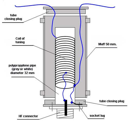
Pic. 4 Final layout of tuning coil and connecting wires inside muff.
Dark blue wires are the connecting wires
A construction turned out impermeable.
All, antenna is ready. We fasten it on a wooden mast (I utillized wood lath 1,7-2 meters) and stick it in earth (better - with stretchings).
I am use coaxial cable of "RG-58U mil" long in a electric wave (19,52 meter).
Antenna was set before a house, in 12 meters from a wall. A cable is buried in ground on a small depth (about 10 cm.). The bushed of lilac and big trees grow next to antenna (around, in 1,5 - 2 meters from antenna, see Pic.5 and Pic.10), far higher than antenna.
Original appearance of the set antenna can be seen on the picture of Pic.5
|
|
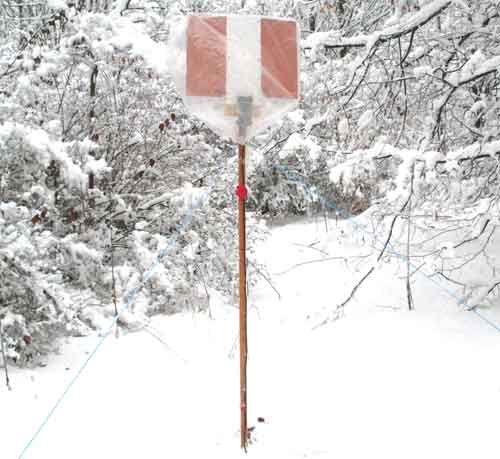
Pic.5 Flat EH antenna stand up 1,5 meters from the ground, it rains :)
|
I then characterised the various parameters of the flat EH antenna on 10 Mhz , (see Pic.6 below).
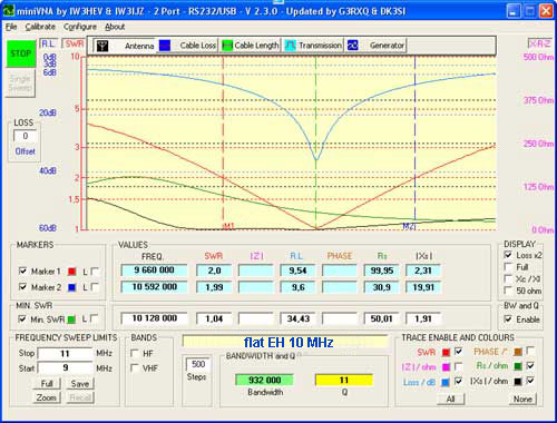
Pic. 6 Characteristic of flat EH antenna 10 MHz.
All antenna parameters are good. The passband is 930 KHz with a SWR = 2:1 which is more than sufficient for our allocation on the amateur band of 10 Mhz. Please note that I include ferrite RF chokes which are made by twisting a few turns of coax on a ferrite ring. The choke is located about 15 cm from the base of the antenna.
Grounding:
In previous articles I wrote that EH antennas require good ground conditions, possibly more so than conventional Hertzian antennas. There are a number of reasons for this and I will expand on good ground characteristics in a future article. I use a spike rod connected to 1 metre square copper sheet to a depth of 1.5m
The next day it rained all day and this was a good test to see if the rain had changed any antenna parameters.
Pic. 7 Rain in St-Petersburg is a frequent phenomenon.
I turned on my transceiver and noticed that background noises had diminished compared to a 42m long wire and signal levels from many stations were approximately the same on either antenna. My 42m long wire antenna is on the other side of my building, thus there should not be any influence of either antenna on each other. My first station - UA0AV (Siberia, Russia) Sergey from Krasnoyarska, who I have worked many times before and he is a strong signal at my location.. My flat EH antenna was but 1m above ground and I called him.. He returned with a 599!! I worked other stations i.e. M0IOW, RK4HE, SP3OOC whom were considerable distances away but then found myself in QSO with VK3XQ... Australia; unbelievable from such a small antenna!! My report was 539 and his report was 56/7-9. My output power was between 30-40 watts only and my flat EH antenna measuring just 315х460 mm!!!
I have found that the flat EH antenna not only works but works well. I had further QSOs with OK1HAJ, RV3QX, SP9FLO, YU5R, GM0IXO, ON3URT, OZ1HVL, UA4SKW, SP4NDV, UT0EG, DR600UL, RA9FFF, UN1L, RA9JAT, RM9WK, ON3WP/qrp, LA9SN, RD3BD, RV3SBS etc. I then decided to use the antenna to see how it performs under the harsh winters commonly encountered in Russia. The band is a good band to work and I just wanted to know whether there were any differences in performance under all environmental and atmospheric conditions. Using the present design of EH, you can safely use power outputs upto 100 watts for RTTY and PSK and upto 200 watts using SSB or CW.
Flat EH antenna 10 MHz in winter
continuation
Well, it was wintertime in Russia and of course, it snowed. During a three week period I use my flat EH antenna on10 Mhz and had more than one hundred QSOs with 25 countries using an output power of about 30 watts. I was very pleased with its performance. Such a small antenna packs a very big signal!! In general, if I could hear them I could work them. Well, it carried on snowing the EH was covered in snow as was its surroundings. Perfect conditions for what I wanted to test. To my delight I easily made QSO after QSO with the antenna under snow. My impression is that the flat EH antenna continues to work the same way ; with or without a covering of snow. Indeed, when I measured the antenna parameters, they appeared the same as when I measured them one month ago. There were days, when wet, sticky snow accumulated on the antenna but I had no difficulties working other stations around the globe (see Pic. 8 on snowfall at this stage).
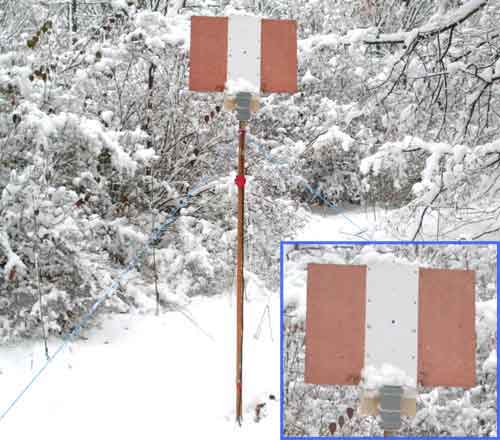
Pic. 8 Snow on EH antenna not too bad relative to Russian winters and snowfall :)
The snow melted and in a few days it all disappered. I decided to remove my flat EH antenna and see how it fared after one month of a Russian winter. All appeared OK apart from a drop of water from the bottom of the muff. I took the muff off and found that it had collected about 10g of water inside. There was not much water inside but it was necessary to understand how it got there so that future antenna builds do not suffer from this problem of water ingress. (see Pic.9).
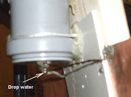
Pic. 9 Drop after a drop with the bottom enclosure closed.
And when I opened a tube closing plug... here and outpoured about 10 gramme of water. And it got in a muff on the twisted up wire, to going from a spool to the copper "shoulder" of antenna. Therefore conclusion - it is necessary to skip the conclusions of spool through clock-houses impermeable hobs. To one only glue it is not enough from a glueing pistol.
And when I opened the bottom enclosure out poured about 10 gramme of water. It got into the muff via the twisted pair wires. It was then necessary to take apart the antenna, let it dry and re-check parameters (and they did not change). I then put the antenna back in the garden and my conclusion is that the glue is not enough to prevent water ingress and I put the antenna in a polyethylene bag (see Pic below).
Pic. 10 EH antenna is in a polybag.
I made further QSOs and everything was working well. This antenna can be tuned for other bands, changing nothing in a construction apart from the length of wires on the tuning coil. Below I present a table that gives calculated data of necessary coil turns for their respective bands.
It is clear that this little antenna mounted just 1 Ц 1.5m above ground is very efficient and in order to understand something of its persona, you must build it and see how it works.
| Band MHz | calculated data of coil |
| 7 MHz | 76 coil* |
| 10 MHz | 39 coil* |
| 14 MHz | 24 coil* |
| 18 MHz | 17 coil* |
* two twisted up wires of #21 (0.85 mm)
Well, month is over... and already "produced" on this antenna so much stations on a band 10 Mhz, that got a award (photo of Pic. 11 below). Means all the same it is possible to work on such EH antenna at such powers and at the height of aerial a 1,5 meter from the ground!
Well, my month of wintertime operating is over... and I worked so many stations on this band that I earned an award (see Pic. 11 below).
PRACTICE - is the best criterion of theory!

Pic. 11 Award # 802 "EPC30 Bronze", for work on a band 10 Mhz on EH antenna of the month.
73!UA1ACO
11.2009г.